6 Pin Ignition Switch Wiring Diagram
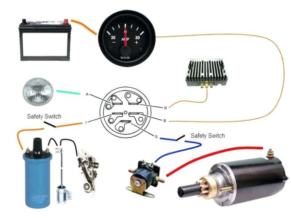
View 6 Pin Ignition Switch Wiring Diagram PNG. A wiring diagram is a simplified standard pictorial representation of an electrical circuit. There are 2 rows of pins, 3 pins in each row, the middle one is the common terminal, corresponding to the two left and right pins, one is normally.
Black anti vandal toggle switch.
Cdc (ignition/accessory power for cd changer, phatbox, oem or aftermarket ipod interface etc) 11 if no sds, then you will connect the mic wires directly between your oem bluetooth kit and the bt mic this pin should be connected to connector i, pin 2 from symphony ii radio harness, or to the large. Note that the subaru wiring diagram numbers the pins differently than on the scoobymods picture above ***8212; Ignition switch & lock cylinder. 6 p switch schematic diagram and connection method:

0 Response to "6 Pin Ignition Switch Wiring Diagram"
Post a Comment